Our products: vertical turbine pump, vertical wet pit pump, vertical oil sump pump, vertical condensation pump, right Angle gearbox
DATE:2024/11/20 16:42:06
Visits:
2. Clean the headshaft threads. Lubricate the threads and try installing the adjusting nut (it should thread on by hand easily, if not, clean up the threads with a fine three cornered file).
3. Clean the driver mounting flange and remove any burrs or nicks on the register and mounting flange. Oil lightly.
a. Check the shaft diameter and projection against coupling and schematic provided.
b. If the dimensions are correct proceed to step 4.
c. If the dimensions are incorrect contact the nearest manufacturer's representative for assistance.
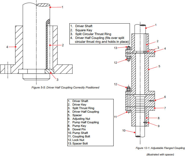
4. Install the driver half coupling on the driver shaft (refer to Figure 5-5 for coupling illustrations).
a. Place the straight key into the keyway. Ensure that the key is up far enough to clear the circular
groove cut around the shaft, near the end. Hand press the key into groove.
b. Slide the driver half coupling onto the motor shaft far enough to insert the split circular thrust ring into the shaft groove. The coupling must be a tight fit to the driver shaft but not interference fit.
c. Install split circular thrust ring in the shaft groove. When properly positioned the motor half coupling will slide down over the split circular key and hold it in position (refer to Figure 5-5 ).
5. Install the mechanical seal at this time if the vertical turbine pump is so equipped and the mechanical seal was shipped uninstalled.
6. Install the vertical turbine pump half coupling onto the headshaft:
a. Slide the vertical turbine pump half coupling onto the shaft.
b. Install the key and push down to clear the threads.
c. Thread the adjusting nut (right hand threads) onto the shaft until the end of the shaft is even with the top of the adjusting nut.
7. Center the motor over the vertical turbine pump and rotate to align the mounting holes and properly align the power conduit box. For gear drives, rotate the input shaft into desired position.
8. Lower the driver carefully into place ensuring that the driver and pump registers mate correctly. Check the shaft gap between the motor and pump shaft against the schematic provided.
9. Bolt the driver to the discharge head.
10. Refer to the driver manufacturer’s instruction manual for specific product requirements regarding installation and start-up procedures.
CAUTION:DAMAGE TO the vertical turbine pump
• Before jogging the motor make sure the coupling halves are not touching and the motor shaft end is sufficiently clear of the vertical turbine pump shaft and adjusting nut, and the driver can rotate freely without rotating the vertical turbine pump. The driver half coupling must be in proper position as shown in Figure 5-5 so that the split circular thrust ring does not come out.
• Always check rotation before connecting the driver to the vertical turbine pump as reverse rotation while the vertical turbine pump is connected can cause extensive damage to the vertical turbine pump.
11. Check the electric driver for rotation at this time. Establish electrical connections and run the motor briefly to check the rotation. Driver must rotate in counter clockwise direction when viewed from the top end of the motor.
a. To change the direction of rotation on a three phase motor, interchange any two line leads.
b. To change direction of rotation on a two phase motor, interchange the leads of either phase.
12. For pumps using a spacer type coupling, bolt the spacer to the driver half coupling.
13. Thread the adjusting nut up until there is 1/8 gap between the nut and the spacer or driver half coupling (refer to Figure 5-7).
14. Adjust mechanical seal after adjusting the impellers.

Copyright © 2002-2022 Hunan machinery manufacturing co., LTD. All Rights Reserved.
+8618507312158

WeChat Qr Code